Rotary Vane Compressor
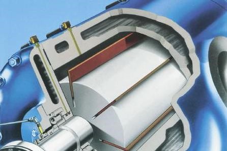
Rotary Vane Compressor

Principle

A single rotor is mounted offset in a cylindrical housing. Slots in the rotor contain vanes, which are thrown against the wall of the housing as it rotates.

Oil is injected into the compression space to lubricate the bearings and vanes. As the rotor is offset, the segments that are created by the vanes vary in size through the cycle, causing the trapped gas to be compressed.

Ports in the housing wall are positioned to let the gas in and out at the points of minimum and maximum pressure. Fully oil flooded versions are also available, with no oil loss to process.

Typical Performance Envelope
 
  Imperial Metric
 
Minimum swept volume 5 cfm 8 m3/h
 
Maximum swept flow 3,500 cfm 6,000 m3/h
 
Maximum casing pressure 250 psi 17 bar
 
Maximum pressure ratio per stage 3.5  
Advantages
 
  • Slow speed of rotation means low wear.
  • Single rotor and vanes are only moving parts.
  • Once-through oil lubrication means no build up of aggressive contaminants. Film of oil protects internals from attack.
  • Vibration free operation.
  • High speed range, typically -50% +20% from standard, gives easy flow control through speed variation.
  • No special foundation required, lowering civil costs.
  • Can usually be direct driven – doing away with belts or gearboxes.
  • Pulsation free gas discharge.
  • Valveless porting means no drop off in efficiency between overhauls, and no valves to maintain or break in service.
  • Very economic to purchase and maintain – vanes and bearings are only wear parts.
  • Simplicity: units are readily overhauled in the field without special tools.
Disadvantages
 
  • Intimate contact between lubrication oil and compressed gas.
  • Small quantities of lubrication oil need to be disposed of after use.
  • Low pressure capability as single stage unit.
Common Applications